Already in the planning phase you can have a look over further details for the lighting solution. One thing is the wiring and installation of lighting directly into the bookcases, the other thing is the wiring behind and on the library system and the installation of ballasts and controls for the lighting system. We remember that 26 supply lines had to be led out from behind the bookcases and finally brought together on the library system in junction boxes.
We also remember: the connecting cables to the LED strips are designed in 2×0.75 mm². The 0.75 mm² cross-section is a good compromise in line flexibility and sufficient cross-section to minimize voltage losses. Much larger cross-sections are difficult to solder to the LED strips.
Four junction boxes for connecting wires are installed on the library top. The junction boxes are interconnected with NYM 3×1.5mm². From a box it then goes with NYM 3×2.5 mm² and 5×2.5 mm² to the distributor board, which is installed in the attic. Inside the distributor board the ballasts and control electronics are installed. The picture below illustrates the wiring once more schematically.

The supply line from the distributor to the junction box must be made with a 2.5 mm² cable, otherwise the voltage drop would be too great. According to VDE (IEC 60364-5-52 (VDE 0100-520 Annex G)) the voltage drop should not exceed 4% of the rated voltage. The LED strips operate at 24 volts, so the voltage at the end of the last strip should not be less than 23.04 volts. This will also be feasible with the presented cross-sections, which will certainly be used by very few LED strip installers. This is not a major drawback for the secondary side of the ballasts – the only effect of the appearance is that the brightness of the LED strips at the end of an installation chain will decrease slightly. It is anticipated that the largest voltage drop of the installation on the 24V line is 6% (ie 22.8 V). This is negligible for a lighting circuit designed in low voltage, since the human eye can not perceive the difference in brightness (the brightness perception is logarithmic, not linear).
The pictures below show the junction boxes on the top of the library system.


It can be seen that at the junction boxes partially almost all inputs are occupied. The supply lines are either relieved of strain shortly before the junction box or relieved of strain several times directly on the rear wall of the Billy body. To connect / disconnect the junction box I only use Wago 221 connection terminals. Although here the main application of the terminal can be seen, the jamming of rigid conductors and strands I take this terminal in principle in the context of home installation in all junction boxes. The clamp has the advantage that it is very compact and can be easily reconnected by the small lever. In my opinion, the best connection terminal for the wiring of junction boxes (other places of use of the terminal: connecting lamps, in the distributor with the corresponding DIN rail support holder).
The distributor board is sitting in the attic on a wall – it is the heart of the electrical installation. The distributor is installed with a little space to the wall, so that a free back space for the removal of the electr. Power loss in form of heat is guaranteed. A 120×120 mm fan was installed at the rear for the removal of heated air (otherwise the maximum allowable power loss for the distributor under full load would be exceeded). The fan cutout has to be made precisely and a ventilation grille has to be installed. You can use components from the hardware area for computers (they are the same standard 120mm ventilators that are also used in control cabinets).
The Hager VA48CN distributor board makes installation of the components easy. In this case it is used rather as a cabinet as a distributor. It is definitely “prettier” and neater than bolting the ballasts to a wooden board on a wall as it can be seen from time to time. In addition, the devices are installed protected inside the distributor.


The following devices / materials are used, which can be seen in the pictures above:
- Hager Volta VA48CN with Quick Connect terminals (the phase clamp is not included as well as the Hager VZ408 cable clamp) and with door VA48T.
- Meanwell IDLV-45-24, dimmable and others. over 1-10V, flicker-free operation by very high frequencies, it is only a very small minimum load required to dimming (no comparison to previous Meanwell power supplies).
- Eltako FSG71 / 1-10v, Wireless Actuator Dimmer switch control unit for electronic ballast 1-10V .
-
Eltako Wireless Mini Remote Transmitter, & nbsp; FMH8-RW.
- BOPLA TSH 35 DIN rail holder. Ingenious rail carrier can be used very variable. The ballasts and actuators are screwed onto a plastic plate and this plate is bolted to the BOPLA DIN rail holder. It is barely visible on the pictures – an ingenious product for making devices DIN rail compatible.
- Meanwell power supply 12V for the operation of the 12V fan 120x120mm .
- 12 Volt Fan Fractal Design Silent Series R3 120mm, Case Fan; Fan grille 120×120.
- Wago 221 connection terminal and Wago mounting adapter WAGO 221-500.
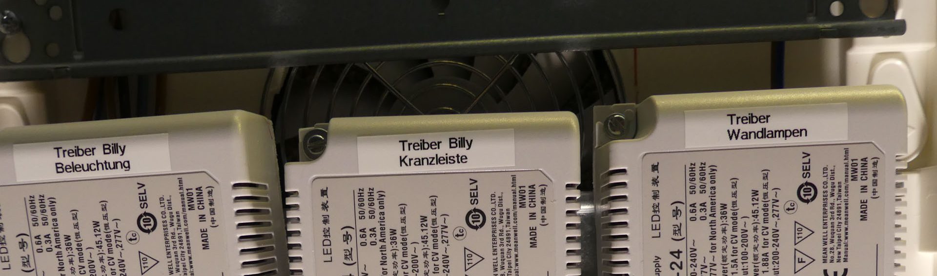
The Eltako wireless actuators switch and dim the Meanwell ballasts. The Eltako system inspired me. It is very easy to teach several transmitters to one actuator. The remote control of type FMH8 that I use does not require any batteries either – the remote control cleverly generates the energy required to send radio telegrams at the press of a button (piezoelectric effect). Actually, at the beginning, I did not plan to install more than two separately switchable lights. After completing the bookcase wall I tested how a top lighting works and came to the conclusion that this looks very good. Thus the originally planned installation has grown a bit. The images represent the current installation. In the middle I will replace the Eltako FSG71 / 1-10v probably against Eltako FAM14 with FSG14 / 1-10V (for the central installation already planned) as the installation threatens to grow by another project.In the distribution board / control cabinet the supply lines and equipment should be labeled so you do no to lose track and make the installation comprehensible to third parties. It serves for the security of persons and equipment if everything can be identified and wired correctly.
Final note: Work on the electrical installation may only be carried out by a trained specialist!