It started with the middle part, which is framed red in the sketchup model. That for several reasons. On the one hand the Billy extensions do not have their own floor and on the other hand special requirements with regard to statics must be considered. In addition the free-floating row of stacked Billy extensions is a key element of the overall design as it is constructed in one piece on the floor and then placed on the two outer Billy bookcases. In my opinio, this was a good constructive solution.

First a suitable and stable base plate had to be found because the deflection without lateral supports is much greater than without. It was out of question to put the bottom plate on the body of the normal Billy bookcases as this would have affected the visual appearance.
The bottom plate of the free-floating Billy extensions is exposed to large forces in later operation. You can count with a hypothetical total load of about 110 kg (5 kg per book series, 4 kg net weight of the Billy extension and 2 kg net weight of the door, ie 11kg x 10). Commercially available chipboard in 16, 19 or 22mm would bend strongly under this load. My choice fell on a 30mm multiplex board (birch). In addition this plate is hung at three points with sturdy hangers after the entire assembly of the bookcases in the masonry of the house inner wall.
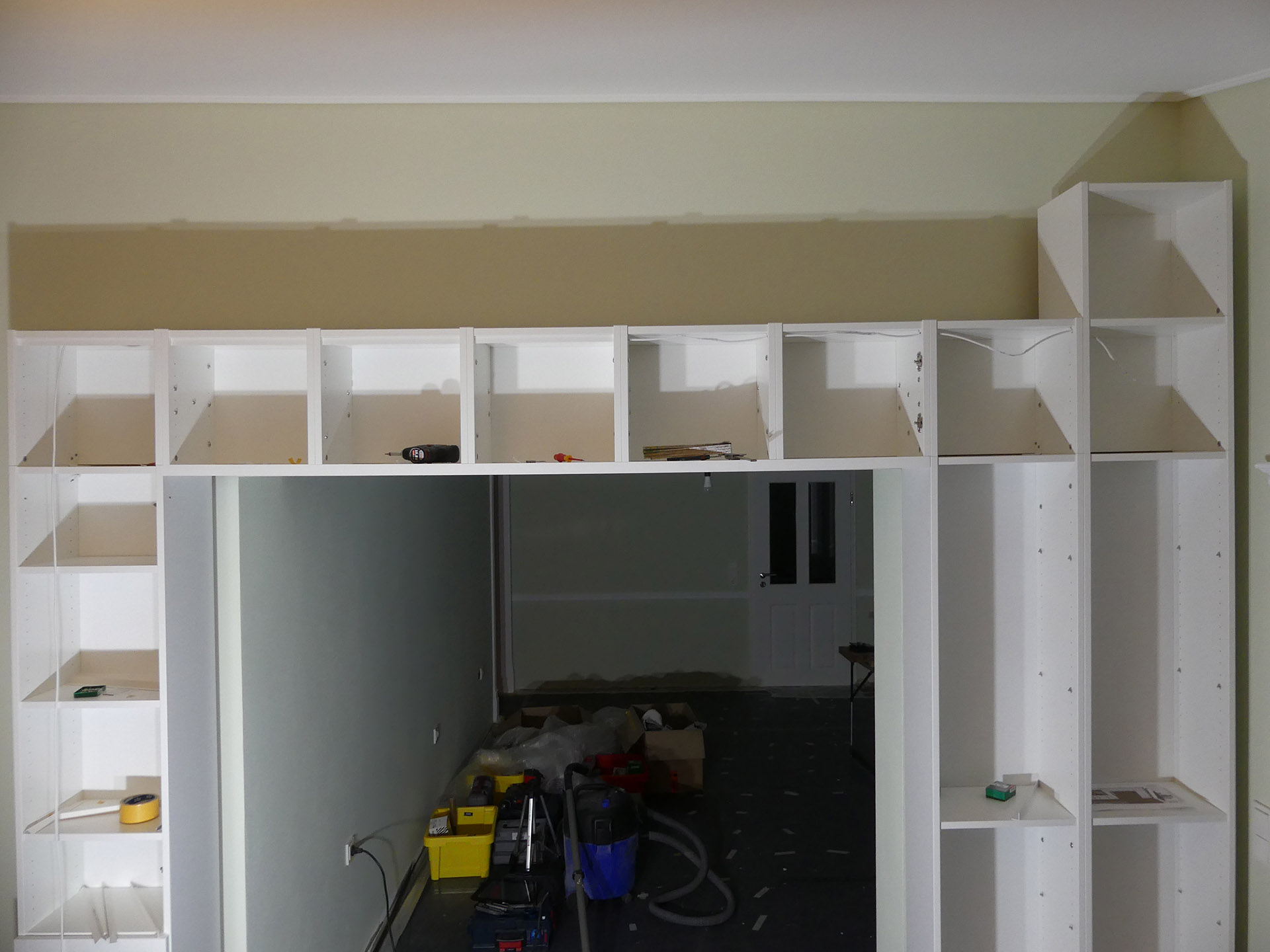
After assembly of the individual Billy extensions these were bolted together with M6 furniture connectors. There were four furniture connectors per side. These are more than enough to absorb the forces. The problem with the top shelf is rather that it is not very stable per se. The rear wall can not be considered as a stable part, since it does not even rest directly on the bottom plate. It is just a blind – in the pictures you can see the little gap to the ground. The largest forces act on the respective outer Billy extensions of the free-floating row (the row is actually not only self-supporting because it will be hung at three points in the masonry in a later stage of construction). But even this is not a problem with appropriate design.


The multiplex board (both top sides with white coating) initially had to be provided with a white edge. Edge trimmers, an iron and sharp cutters are needed here.


After that the plate was put in place to see if everything fits.


The plate was finally glued with the Billy extensions and screwed. The row of screws could only be applied where are later ornamental profiles to cover the screws are attached. Important: The Mulliplex plate must be pre-drilled at the points where the screws sit with a smaller diameter and finally the holes must be lowered to the screw head diameter.
To make the whole thing even stabier the cross-bonding (90 ° to the longitudinal axis of the plate) is highly recommended.


